Beam deflection refers to the bending or displacement of a beam under applied loads. When a load is applied to a beam, it causes the beam to deform, and this deformation is measured as the beam’s deflection. The amount of deflection depends on several factors including the beam’s material, length, cross-sectional shape, and the type of load applied.
In engineering, it’s vital to limit the deflection of a beam within permissible limits to ensure that the structure remains functional and safe. Excessive deflection can lead to structural damage, compromised aesthetics, and, in severe cases, catastrophic failure.
Table of Contents
Factors Affecting Beam Deflection
Understanding the factors that influence beam deflection is essential for accurate calculation and design. The primary factors include:
- Material Properties: The elasticity of the material, denoted by Young’s Modulus (E), directly affects the deflection. Materials with higher elasticity resist deformation better.
- Beam Geometry: The length (L) of the beam and its cross-sectional moment of inertia (I) play a critical role. Longer beams or those with smaller moments of inertia will deflect more under the same load.
- Load Type and Distribution: The nature of the applied load (point load, distributed load, etc.) and how it’s distributed across the beam influence the deflection.
Importance of Slope in Beam Analysis
The slope of a beam refers to the angle of rotation of the beam section under load. It is a critical factor in structural analysis as it provides insight into how different sections of the beam are responding to the applied forces. Calculating the slope at various points along the beam helps in predicting how the structure will behave under load.
1. Cantilever and Propped Beams
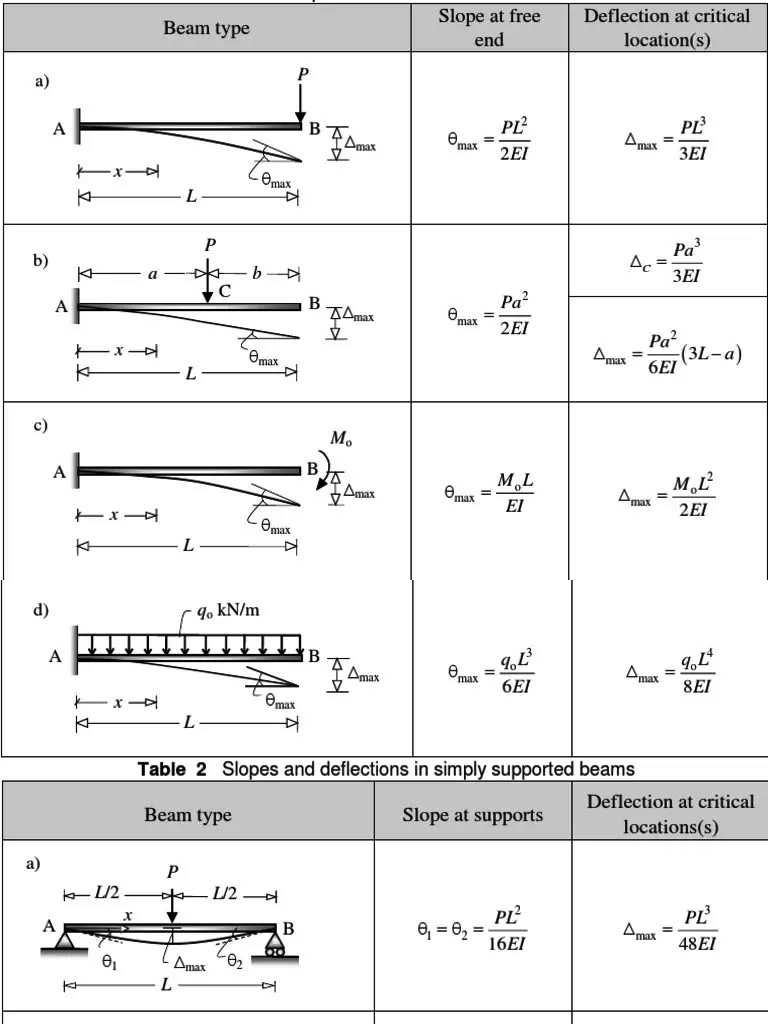
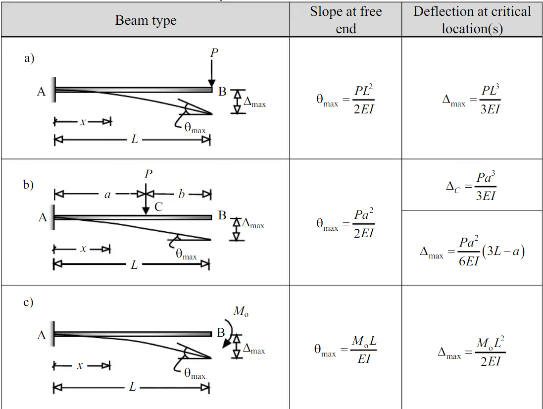
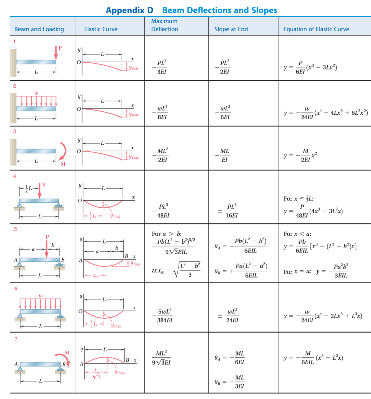
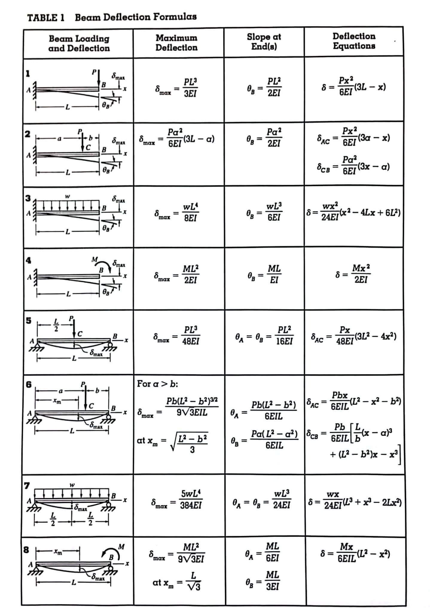
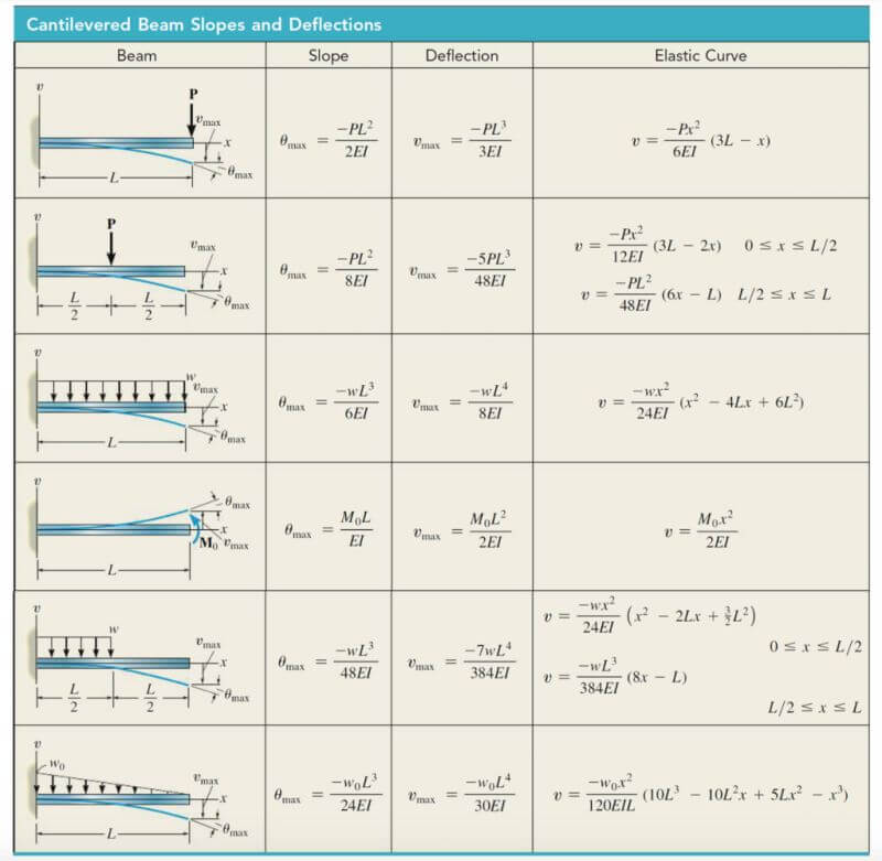
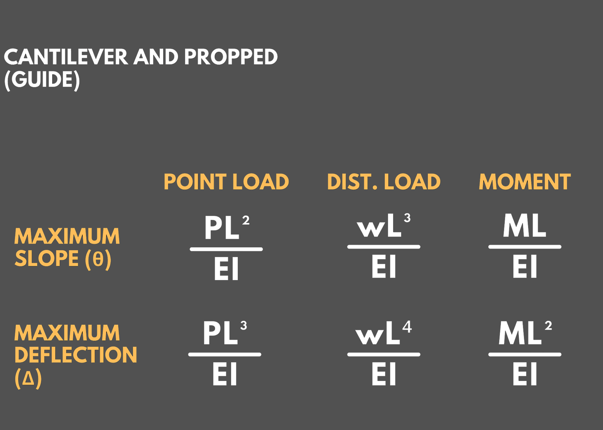
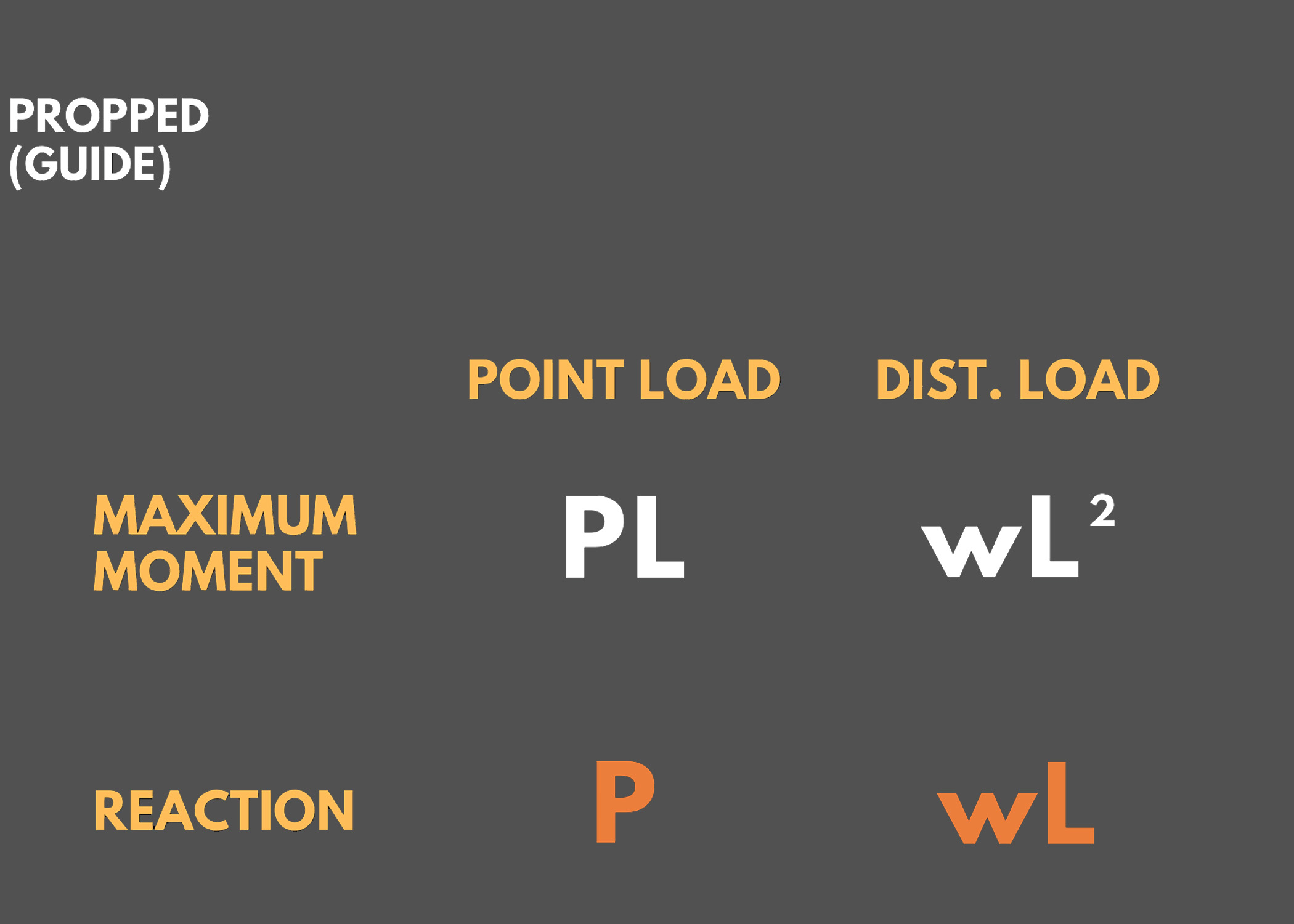
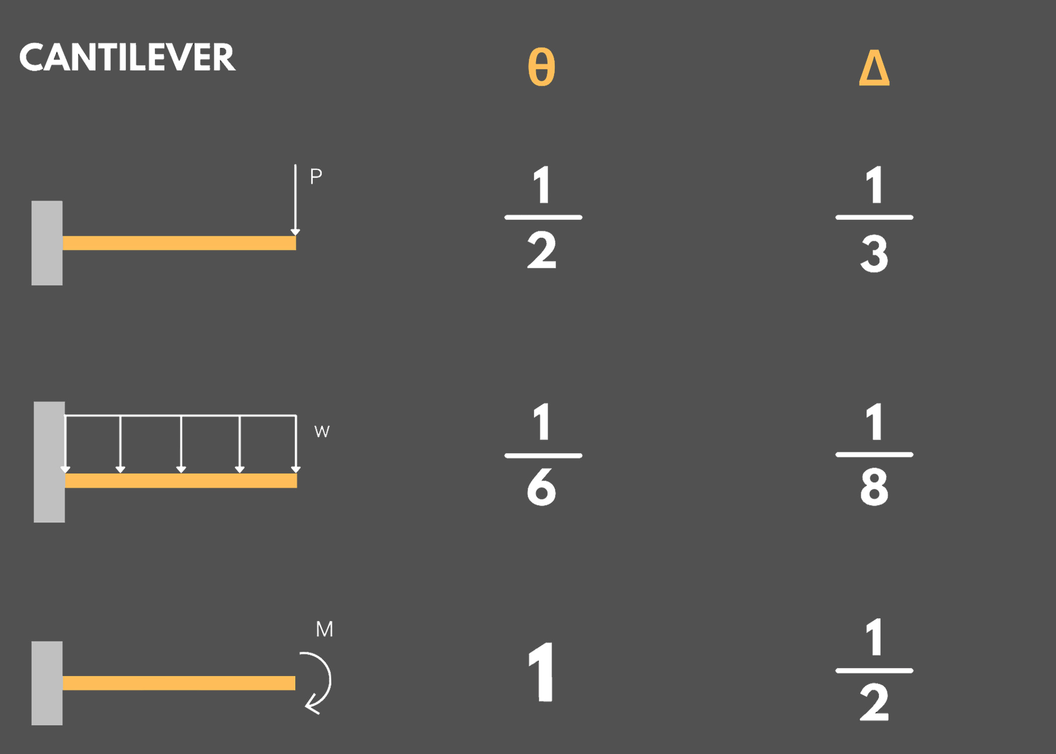
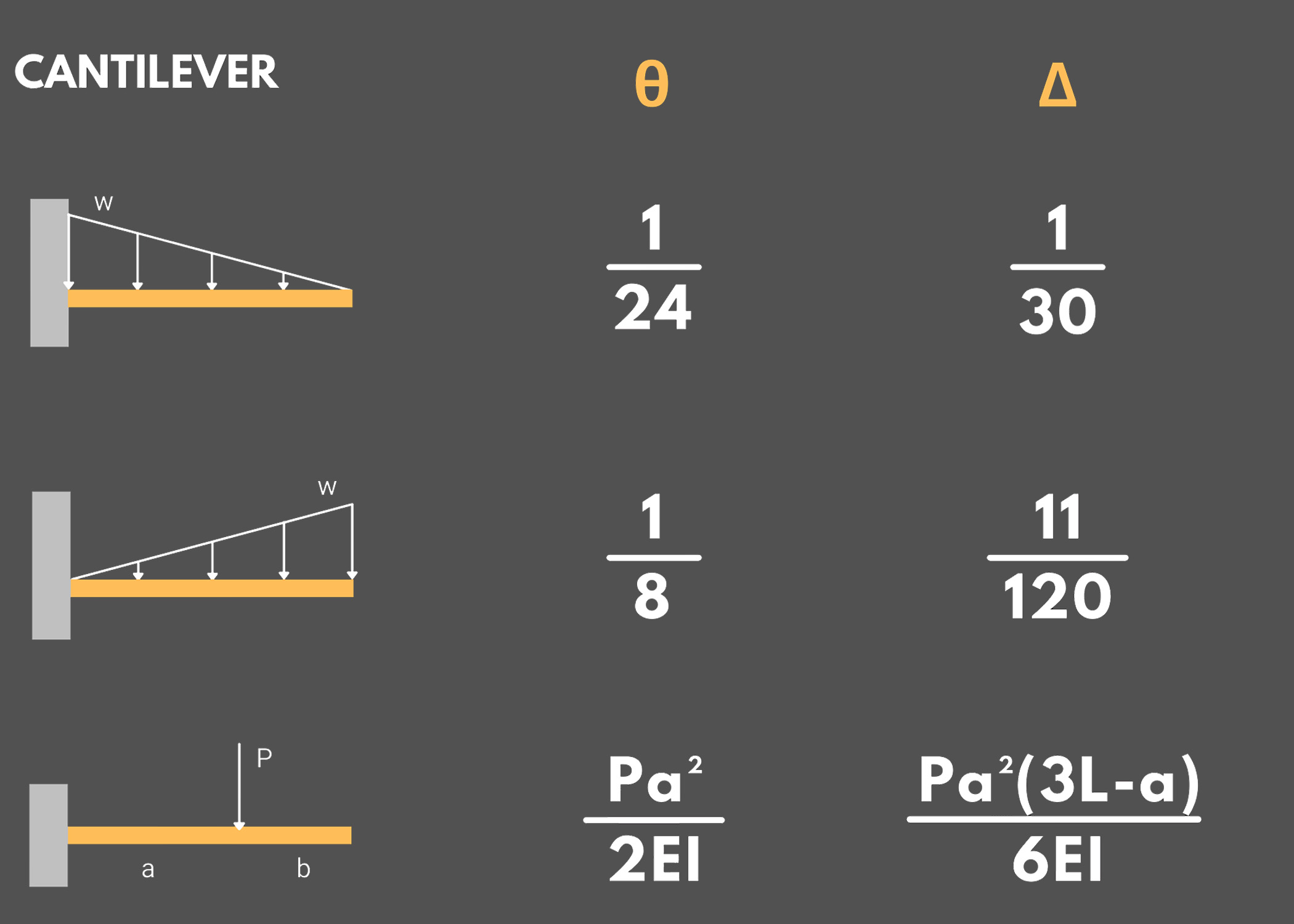
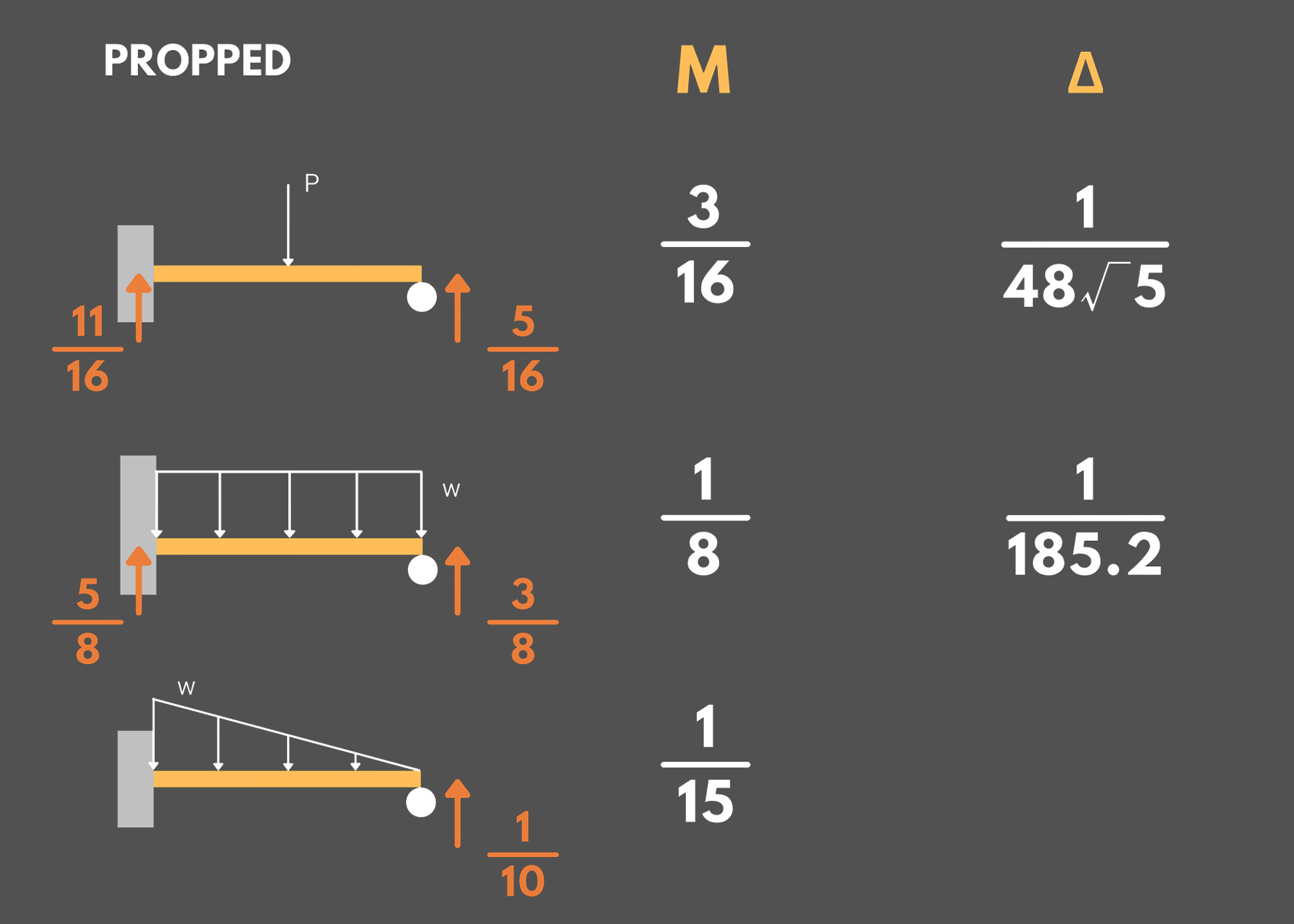
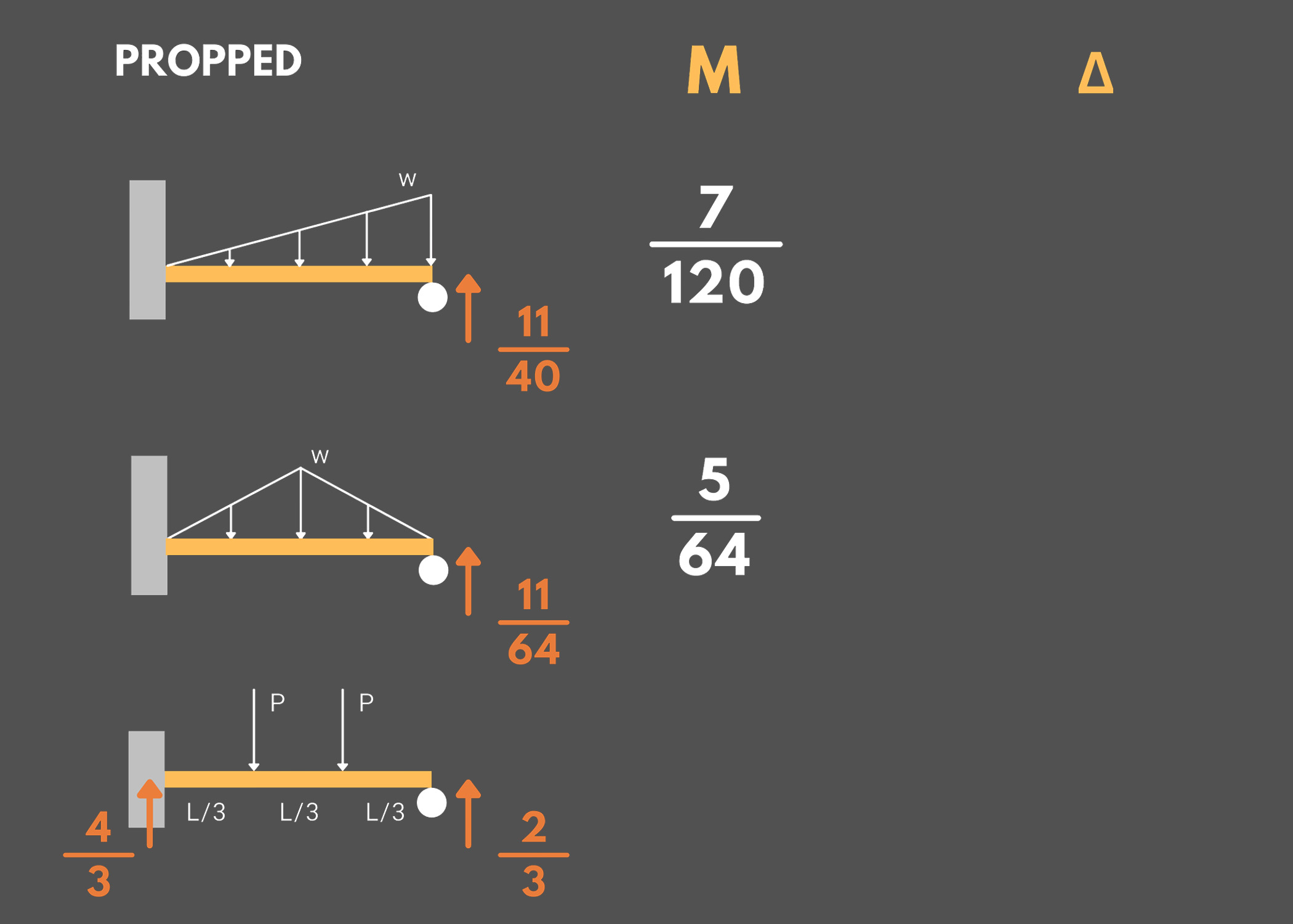
Remember the following formulas to determine the maximum slope, maximum deflection, maximum moment, and reactions of cantilever and propped beams under various loadings.
- Δ: Maximum Deflection
- θ: Maximum Slop
Example:
Propped beam under a uniformly distributed load
- Maximum Moment: wL²/8
- Maximum Deflection: wL⁴/185.2EI
- Vertical Reaction at Fixed End: 5wL/8
- Vertical Reaction at Roller: 3wL/8
2. Simply-Supported Beams
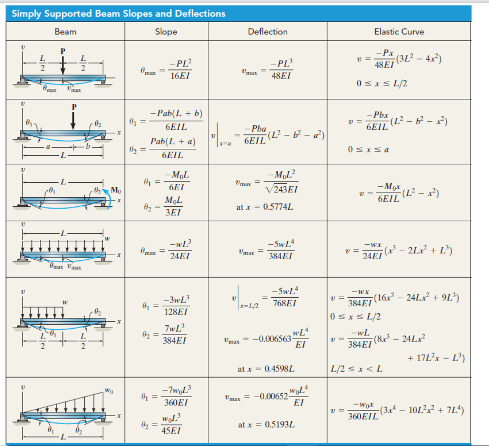
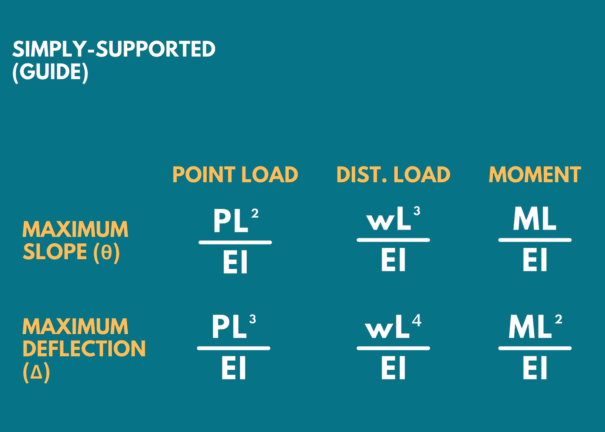
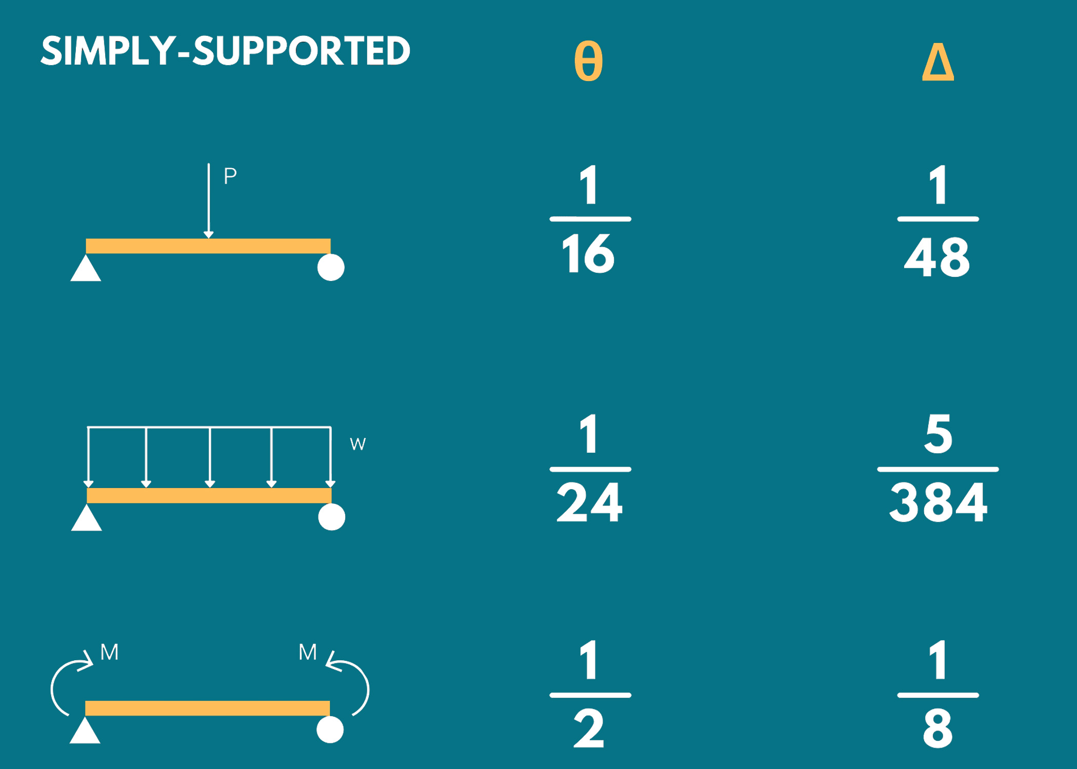
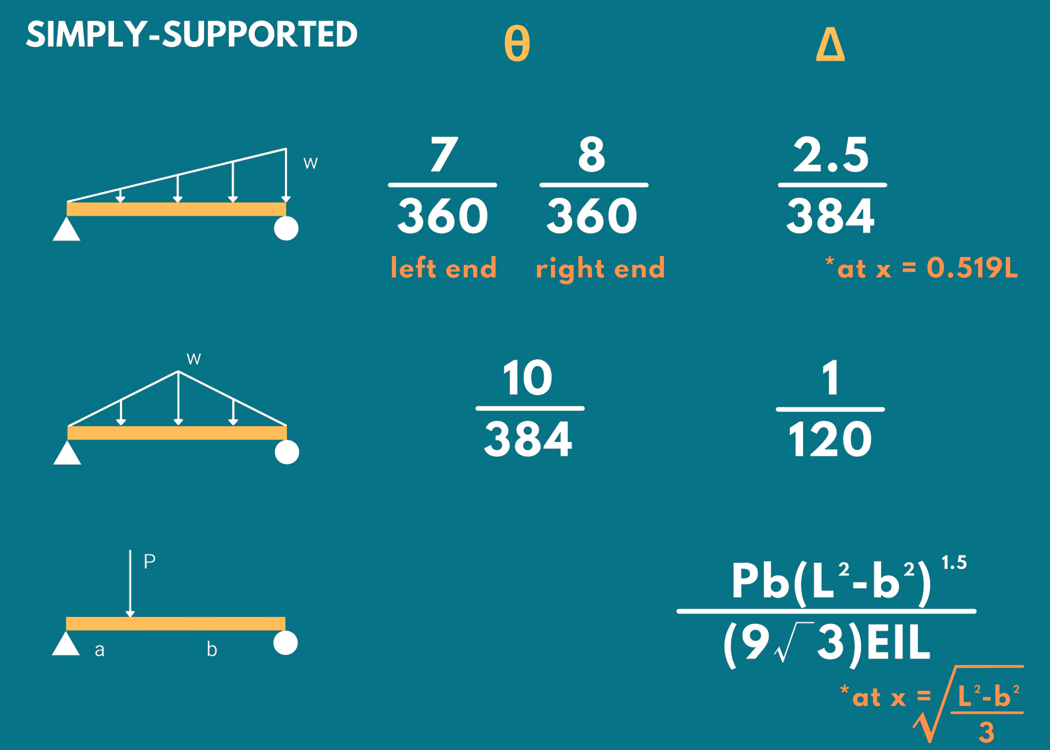
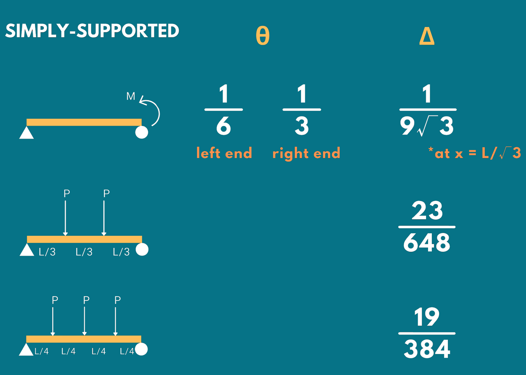
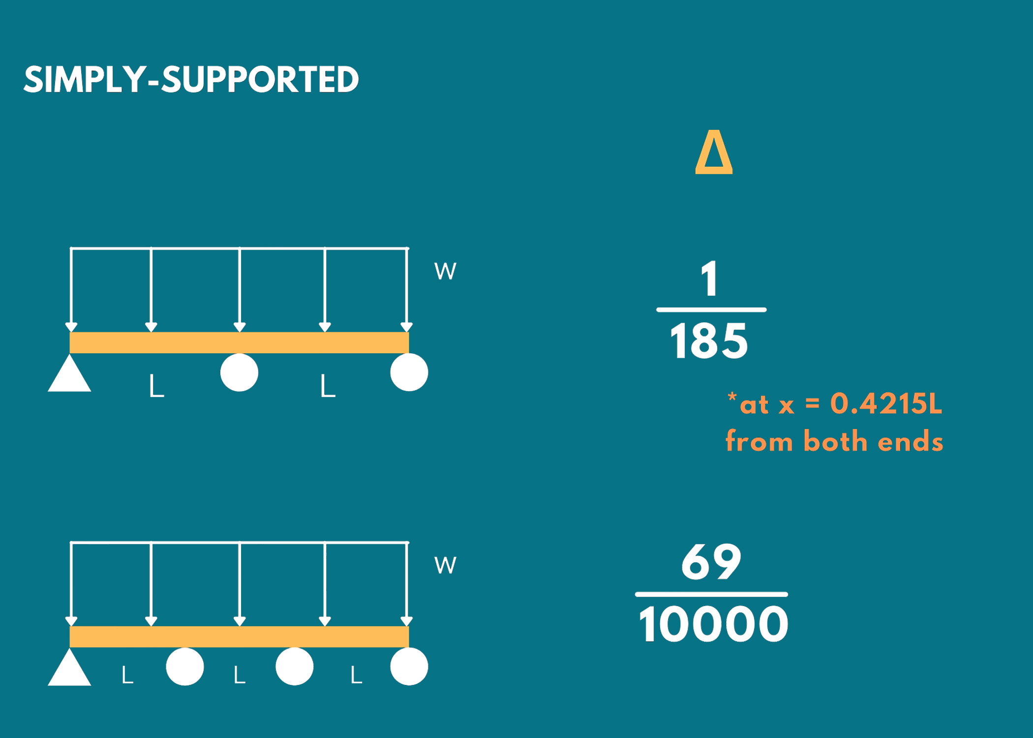
Remember the following formulas for determining the maximum slope and deflection of simply supported beams under various types of loading.
- Δ: Maximum Deflection
- θ: Maximum Slop
Example:
Simply supported beam under a uniformly distributed load
- Maximum Slope: wL³/24EI
- Maximum Deflection: 5wL⁴/384EI
3. Fully-Restrained Beams
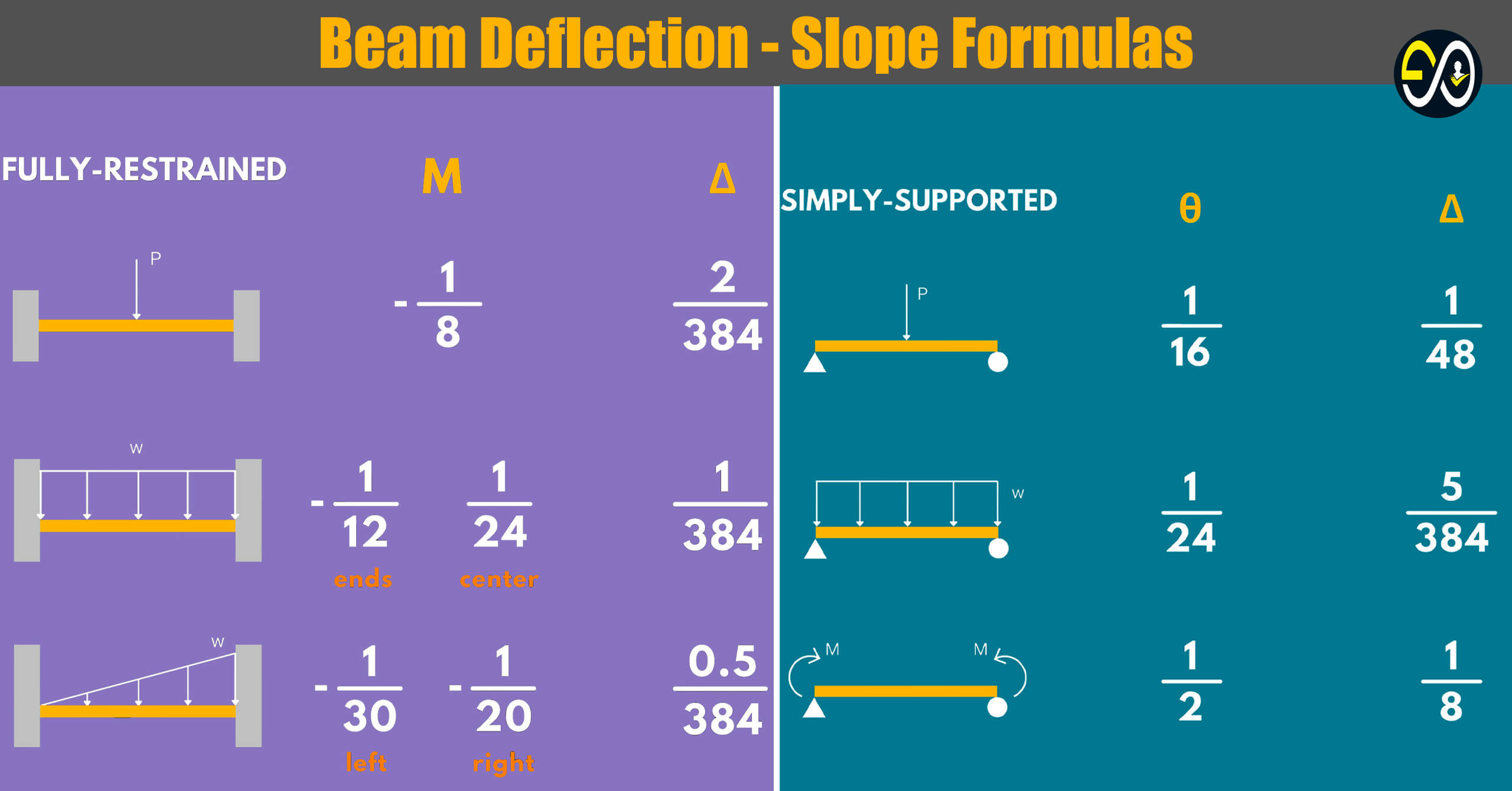
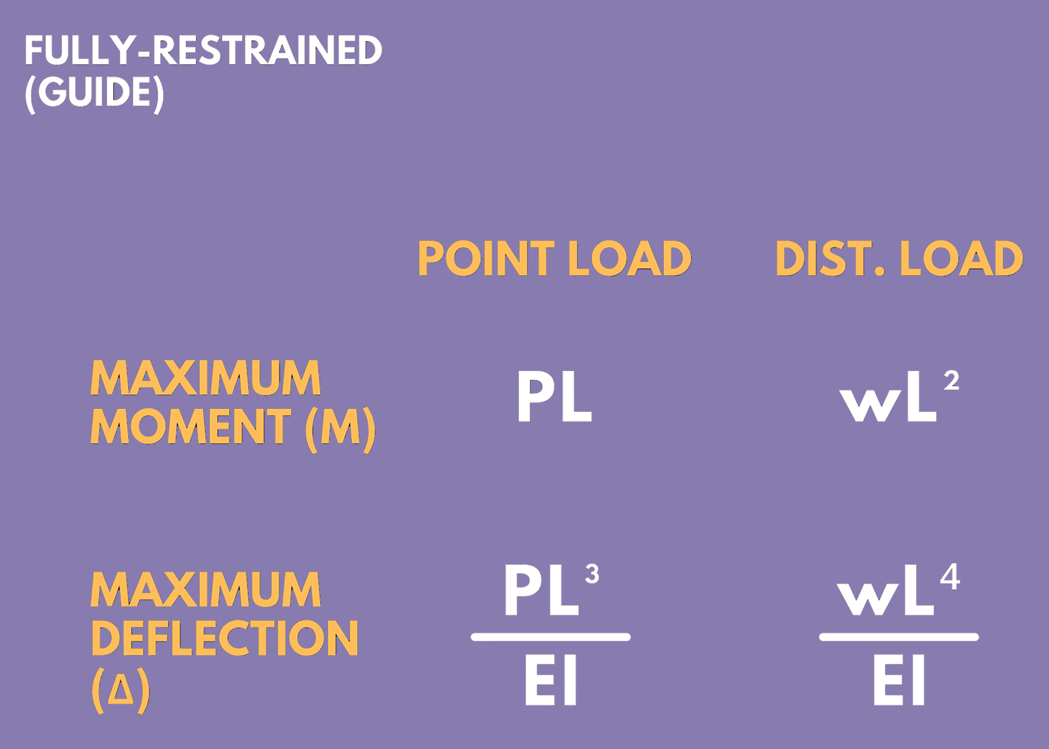
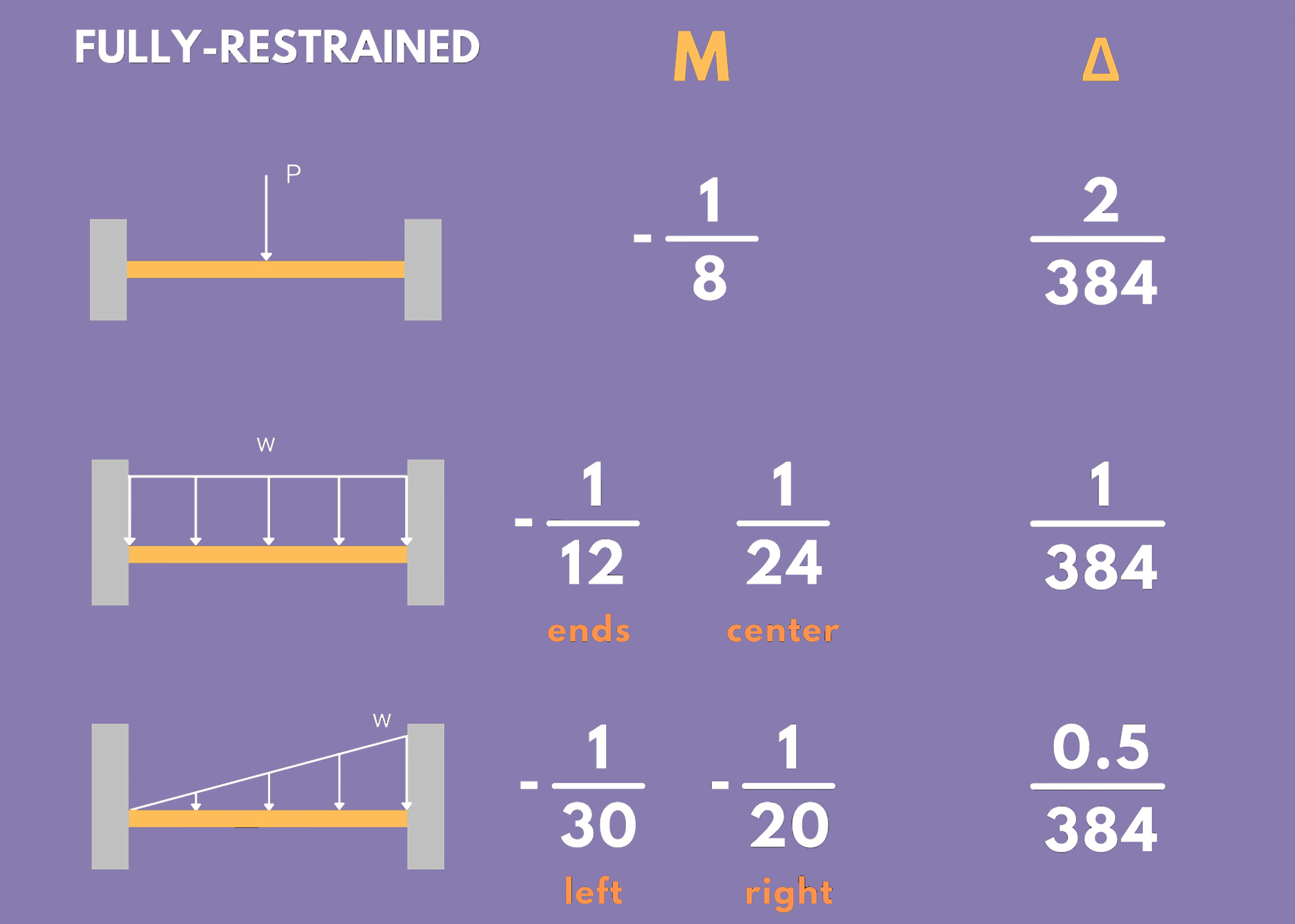
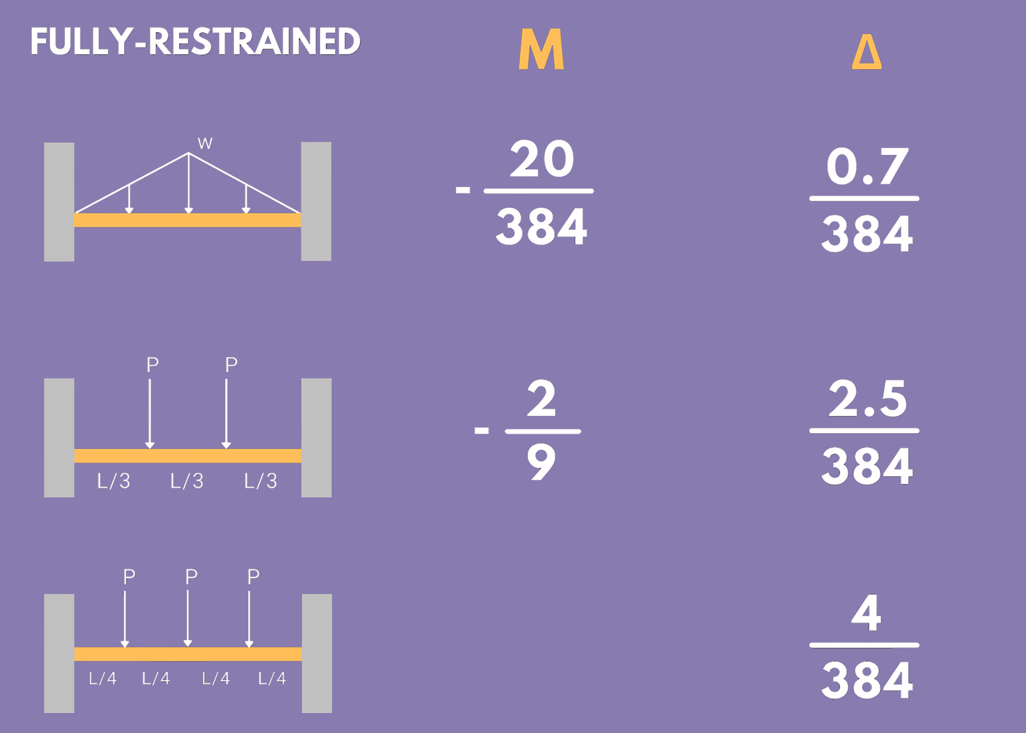
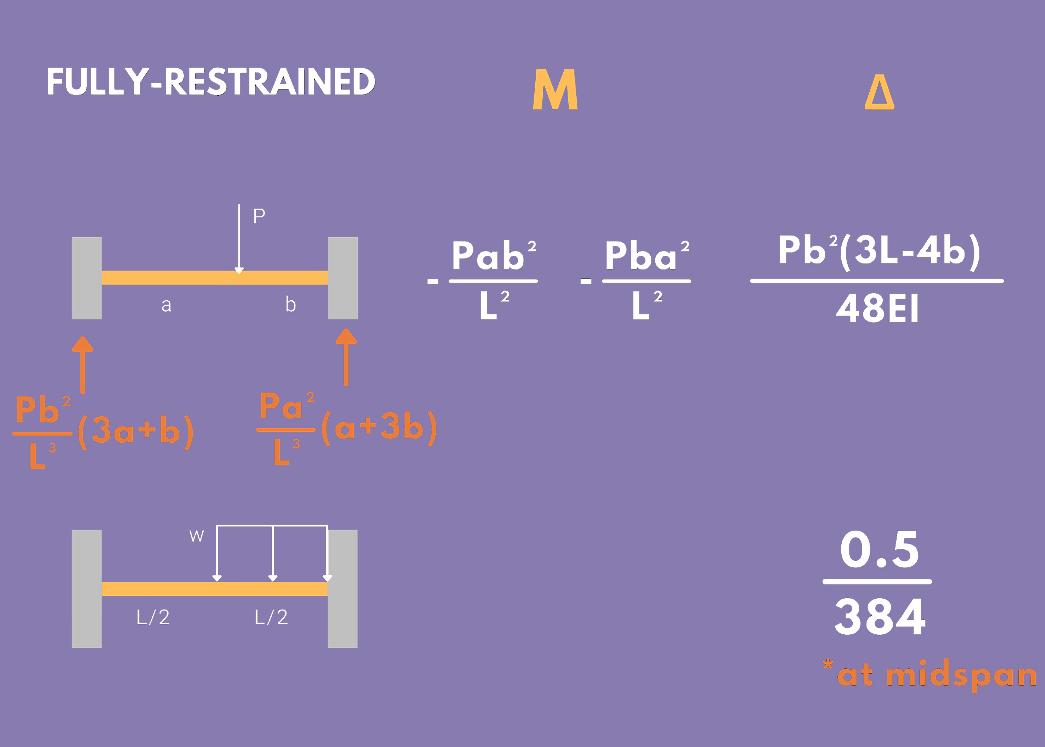
Take note of the following formulas to get the maximum moment and maximum deflection of fully restrained beams under different types of loading.
- Δ: Maximum Deflection
- M: Maximum Moment
Example:
Fully-Restrained Beam under a uniformly distributed load
- Maximum Moment: -wL²/12 at the ends and +wL²/24 at the midspan
- Maximum Deflection: wL⁴/384EI
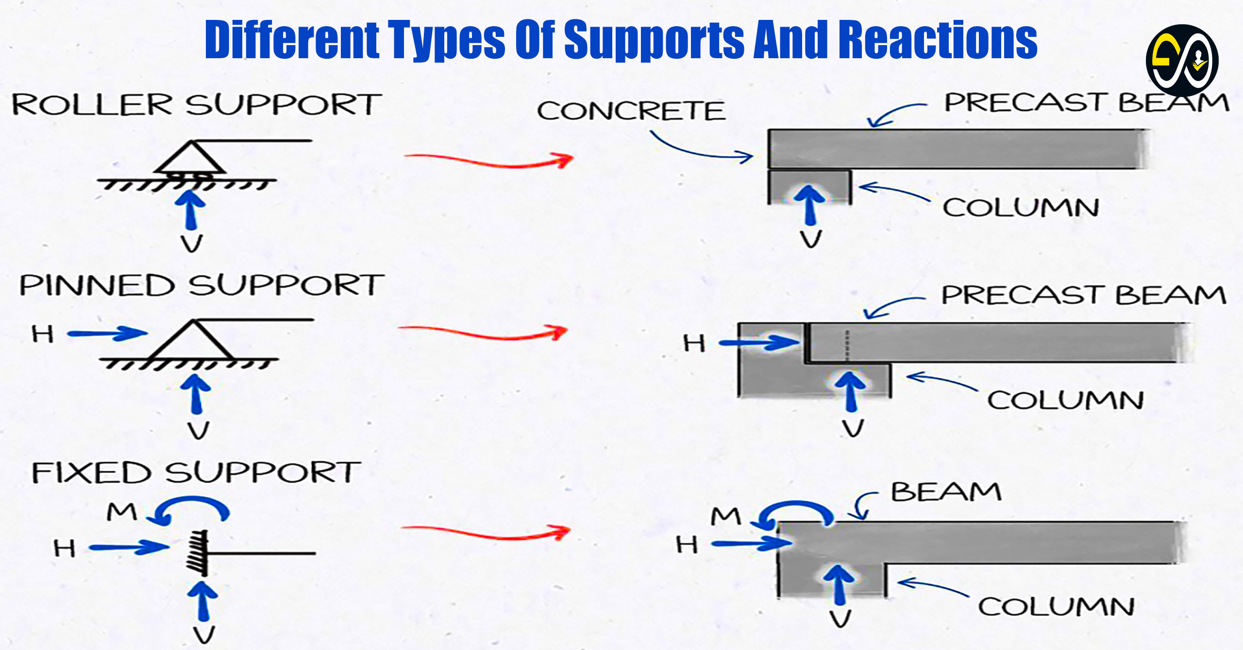
Formulas for Slopes and Deflections of Beams – Additional Helpful Diagrams
